

 Send Email
 Whatsapp


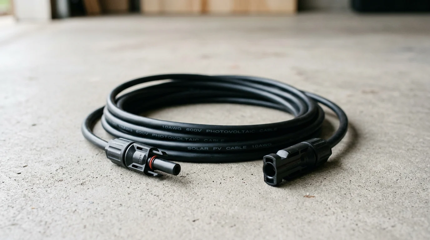
As solar-plus-storage projects expand from rooftops to commercial charging sites, the reliability of every DC connection is becoming a frontline safety and performance issue. A Solar Extension cable is not just an accessory; it is the bridge that carries high-voltage PV output through heat, UV exposure, moisture, and mechanical stress. This article explains how PNTech’s pre-assembled cable and connector solutions support photovoltaic storage and charging applications, why certifications such as UL 4703, IEC 62852, and TÜV 2 PfG matter, and how installers should think about conductor size, voltage ratings, connector compatibility, and the clear distinction between PV extension wiring and battery-side harnesses.


PNTech Solar Extension Cable Connector Solutions
Reliable photovoltaic (PV) and energy storage systems demand robust wiring infrastructure. A complete system architecture spans distinct scenarios: exterior solar array extension cables and interior battery bank harnesses. It is critical to understand this distinction early on: Pv Extension Cables route high-voltage DC from panels and typically use MC4-compatible connectors, whereas battery harnesses handle high-current, low-voltage storage connections with distinct fault-current risks. To meet these diverse needs, PNTech offers a comprehensive portfolio of pre-assembledsolar cables and energy storage connectors. Engineered with specialized jacket options for extreme environments, PNTech solutions meet stringent certifications—such as IEC 62852, and TÜV 2 PfG—ensuring that every deployment operates safely and complies with industry standards.

Role in Photovoltaic Energy Storage Systems
Within a modern PV energy storage system, the extension cable assembly serves as the critical bridge between solar arrays and charge controllers. Because these assemblies include pre-attached, MC4-compatible connectors, they are designed to minimize transmission losses, ensuring maximum DC power reaches the inverter. A poorly specified cable can introduce significant resistance, leading to heat generation and efficiency drops.
Quality assemblies provide secure connections with low contact resistance and appropriate insertion and withdrawal force ratings, preventing power bottlenecks during peak solar irradiance. High-voltage DC systems also introduce severe arc-fault risks; therefore, properly rated disconnects and overcurrent protection are mandatory, especially in combined PV and storage installations. By utilizing high-purity tinned copper conductors, energy is transferred efficiently. In commercial applications, these assemblies must accommodate complex DC requirements such as string combiner limits, strict conduit derating factors, and precise array voltage-drop management.

Key Wiring Terms for Household Energy Storage
Navigating residential solar and storage requires understanding key wiring terms, starting with conductor size, typically measured in cross-sectional area (mm²) or the American Wire Gauge (AWG) equivalent. Standard residential PV setups commonly utilize 4.0 mm² or 6.0 mm² conductors depending on the inverter's maximum input current. For the storage side, critical concepts include matching the battery bus voltage and adhering to precise ring-terminal torque specifications to prevent high-resistance hot spots.
The system's "nominal voltage"—often 1000V DC or 1500V DC for modern rooftop arrays—dictates the insulation rating required to integrate safely with existing infrastructure. Furthermore, the physical locking mechanism on the cable assembly must match the mating hardware. Understanding connector compatibility is crucial to secure connections against weather and mechanical stress. Installers must explicitly note that "MC4-compatible" connectors from different manufacturers are not universally interoperable; mixing genuine Stäubli MC4 parts with third-party clones can violate electrical codes, void warranties, and introduce severe fire risks.
Solar Extension Cable Specifications That Matter
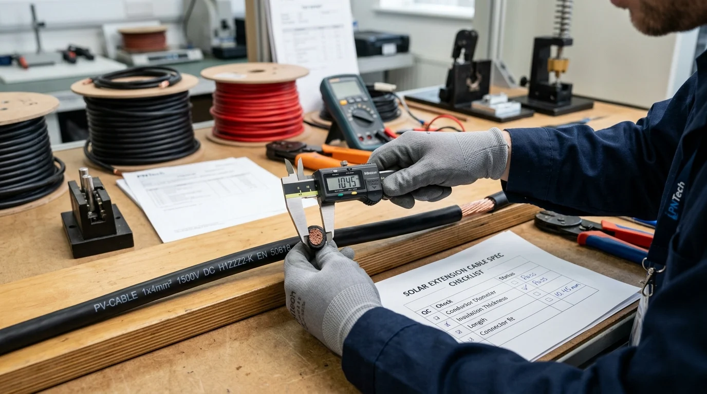
Evaluating the technical specifications of wiring infrastructure is critical for long-term operational success. Selecting the correct parameters directly influences the energy yield, inherent safety, and lifespan of the entire installation. Overlooking these metrics can lead to thermal degradation of the insulation, increased resistance, and costly system downtime.
Current Capacity and Cable Sizing
Current carrying capacity, or ampacity, is the foundational metric used to determine proper cable sizing. When sizing a system, the conductor must safely handle the maximum short-circuit current of the solar array multiplied by a safety factor (typically 1.25 to 1.56 depending on local electrical codes).
Below is a comparative table illustrating typical sizing capabilities for cross-linked polyolefin (XLPO) cables based on a 60°C ambient temperature baseline:
| Cable Size (mm²) | Nearest AWG Equivalent | Typical Ampacity Range (A) | Max Conductor Resistance at 20°C (Ω/km) |
|---|---|---|---|
| 4.0 | 12 | 40 - 55 | 5.09 |
| 6.0 | 10 | 50 - 70 | 3.39 |
| 10.0 | 8 (Note: falls between 8 and 6 AWG) | 70 - 98 | 1.95 |
Note: The ampacity figures provided are baseline ranges assuming a specific conductor temperature rating (e.g., 90°C) and a free-air baseline, not universal code compliance. Direct-burial applications, conduit fill limits, cable bundling, high altitude, and soil thermal resistivity all require additional derating beyond the single 60°C ambient baseline shown. Always consult applicable electrical codes for precise ampacity limits based on specific conductor temperature ratings and installation methods.
By consulting these metrics and applying the necessary derating factors, the selected wiring mitigates excessive voltage drop over long runs, keeping the system operating within optimal parameters.
Safety, Durability, and Installation Trade-Offs
Balancing safety, environmental durability, and ease of installation requires careful material engineering. Electron-beam cross-linked materials provide cables with exceptional thermal stability, allowing them to operate continuously in extreme temperature ranges from -40°C up to +90°C, and withstand short-term spikes up to 120°C.
However, there is an inherent trade-off between maximum durability and installation flexibility. Thicker, heavily armored jackets provide superior UV and ozone resistance for harsh outdoor environments, but they require larger bend radii. To make this actionable, installers should maintain a minimum bend radius of typically 4 to 6 times the cable's outer diameter. For tight residential inverter enclosures, the robust IP68-rated weatherproofing—which applies specifically to the fully mated connector assemblies rather than the cable jacket alone—must be balanced with sufficient cable flexibility to prevent undue mechanical stress on the joints and terminals.
How to Choose the Right PNTech Solar Extension Cable
Selecting the optimal wiring infrastructure requires a systematic approach tailored to specific project parameters. Whether outfitting a massive commercial facility or a compact residential setup, the procurement process must guarantee compatibility and performance. For large-scale deployments, specifying PNTech's customized jacket colors or specialized lengths ensures precise architectural and safety requirements are met without compromising electrical integrity.
Practical Selection Steps by Use Scenario
The selection process starts by calculating the maximum anticipated current and measuring the physical distance between the solar arrays and the inverter. This allows for the calculation of the expected voltage drop. Instead of an abstract "keep below 2%" rule, installers should use the standard DC voltage-drop formula: Voltage Drop (V) = (2 × Length in km × Current in A × Cable Resistance in Ω/km). For example, a 50-meter (0.05 km) run carrying 20A on a 6.
Key Takeaways
- Specify PV extension cables and battery harnesses separately because high-voltage array wiring and high-current storage wiring have different connector, protection, and fault-current requirements.
- Use certified components such as UL 4703 PV wire, IEC 62852 connectors, and TÜV 2 PfG cable designs to support safe outdoor operation and code-compliant installations.
- Select conductor sizes such as 4.0 mm² or 6.0 mm² only after checking inverter input current, cable length, voltage drop, and installation derating factors.
- Verify connector compatibility instead of assuming all MC4-compatible products can be intermated, since mixed brands may create code, warranty, and fire-safety risks.
- Control resistance at every connection point with low-contact-resistance connectors, proper locking mechanisms, and correct terminal torque to reduce heating and power loss.
Frequently Asked Questions
What is a solar extension cable used for?
A solar extension cable routes high-voltage DC power from PV modules to charge controllers, inverters, or combiner boxes. It extends array wiring while maintaining secure, weather-resistant connections when properly sized and certified.
How is a PV extension cable different from a battery harness?
PV extension cables typically carry high-voltage DC from solar panels and use MC4-compatible connectors. Battery harnesses handle lower-voltage, higher-current storage connections and require different terminals, torque control, and fault-current protection.
Which certifications matter for solar extension cables?
Important certifications include TUV for PV wire, IEC 62852 for connectors, and TÜV 2 PfG for photovoltaic cable performance. These help confirm insulation, durability, and safety under outdoor solar conditions.
What cable size is common for residential solar systems?
Many residential PV systems use 4.0 mm² or 6.0 mm² conductors, depending on inverter input current, cable length, voltage drop limits, installation method, and local electrical code requirements.
Can all MC4-compatible connectors be mixed together?
No. MC4-compatible does not always mean interchangeable. Mixing genuine MC4 connectors with third-party clones can violate codes, void warranties, and increase fire or arc-fault risk.